
 |
Lift Pumps, Force Pumps, Semi-Rotaries & Chain Pumps |  |
|
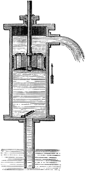
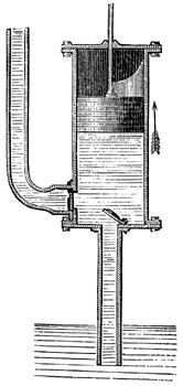
| The lift pump and the force pump are two very basic forms of pump, the theory of which is pretty straightforward. Both make use of a downpipe, a barrel (also known as a cylinder), a plunger (also known as piston), a couple of valves, and an outlet spout or pipe. The following graphics are taken with permission from http://etc.usf.edu/clipart. | |
 |
 |
| The lift pump (above), also known as a suction pump, operates as follows: on the upstroke of the plunger, the lower valve opens, the upper valve (situated on or in the plunger itself) is closed, and the low air pressure produced in the barrel allows atmospheric pressure on the surface of the water source, down below, to make the water move up the downpipe and eventually fill the barrel below the plunger. On the downstroke, the lower valve closes, the upper one opens, and water is forced into the barrel above the upper valve. On the next upstroke, the water above the plunger is forced out of the spout, located at the top of the barrel, at the same time as the volume below the barrel fills up with water again. | The force pump (above), also known as a pressure pump, operates as follows: on the upstroke of the plunger, the outlet or delivery valve is closed and the inlet valve opens. The low air pressure produced in the barrel causes the water below to move up the downpipe and eventually fill the barrel. On the downstroke, the inlet valve closes, the outlet valve opens, and the water is forced out via the outlet pipe, which is located at the bottom of the barrel. Water is only expelled on the downstroke, and in order to even out the supply to some extent these pumps, in particular, are often fitted with an air vessel. If you really want to know about air vessels, read on... |
| Just to complicate things further,
the basic lift pump has a limitation in that water cannot be delivered to a
point higher than the spout. The way around this little problem is to use a
delivery pipe instead of a spout, and add a hold-up valve. In this way water
can be pumped vertically to almost any reasonable level (e.g., to an upstairs
cistern), although the top of the barrel needs to be sealed such that water
doesn't escape. This is achieved through the use of a stuffing box. The
resulting set-up is called a lift and
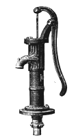
force pump. So, we just need a mechanical device to help raise and lower the plunger and we've got ourselves a village pump. Two types of mechanism are used: the familiar pivoted handle that you heave up and down, and the less common flywheel and crank combination that simply turns rotational movement into the reciprocating action needed to move the plunger. And that's all there is to village pumps: just dig a hole 'til you reach the water source, stick the downpipe into the water and pump away. Er, well, actually, no - in practice there's more to it than this. There's a practical limitation as to how far you can lift a column of water: the vacuum you cause in the barrel by lifting the pump handle certainly causes atmospheric pressure to force the water up the pipe - but only to the point where the weight of that column of water equals the weight of the atmosphere pushing down on the surface of the water source. It may be shown that (oh, the number of times I've used this handy get-out clause...) the maximum height that water can be lifted is about 34 ft/10.3m, at sea level. However, various factors limit this in practice to about 25 ft/7.7m. So if the water source is deeper down than this, the simple set-up as described above can't cope. The answer is to locate the barrel deep down into the borehole or well, even below the water level, when it is termed a "working barrel". Deep Well Pumps This brings us on to the specialised world of Deep Well Pumps, and the topic merits a more detailed explanation. The maintenance of these pumps can be complex, and for a long time I wondered how the sometimes extremely long operating rods were extracted and the valves in the working barrels replaced when they wore out. Eventually I was contacted by someone who had experience of this, going back to the early 1960s, and he willingly produced this account of the process. Thanks very much to Mike Curtis for a fascinating insight. Pump PrimingI've had many questions from people asking about the need to prime their pump: this isn't always necessary as long as there is water in the downpipe and the valves haven't dried out through lack of use. The longer the downpipe, of course, the more effort that is needed in order to raise water to the surface, and in order to ensure that the downpipe is primed it is sensible in the case of a deep well pump to add a foot valve at the bottom of the downpipe. The foot valve is simply an extra clack valve which stops the water draining away, combined with a strainer (also known as a rose) to reduce the likelihood of foreign objects entering the pump (e.g., gravel, weeds, tadpoles, frogs). |
|
| And now it's on to
Semi-Rotary Pumps. And also Chain Pumps. |
|