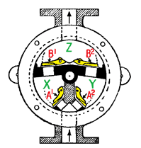
The wing is a close fit within the inner face of the metal casing and is oscillated through about 110 degrees by means of a handle fixed to a central spindle. The space below the wing is divided into two chambers, X and Y, and the space above the wing is another chamber, Z.
When the wing is rotated in a clockwise direction, pressure is lowered in chamber X, valve A1 opens and water enters the chamber. At the same time, valve B2 opens, and water already in chamber Y from a previous pump of the handle flows into chamber Z. On the reverse stroke of the handle, valves A1 and B2 close and valves A2 and B1 open, water flows up into chamber Y and that in chamber X is forced into chamber Z, which if it is already full results in water being expelled out through the delivery pipe. Subsequent oscillations of the handle maintain the delivery of water alternately from chambers X and Y, into Z, and out via the delivery pipe.
These simple pumps are widely available today, are easy to maintain and are commonly used for pumping kerosene and fuel oil, as well as water. They are often called "K-type" pumps, as most of them carry a K number, from K0 to K7, on their covers, which refers to the diameter of the inlet/outlet bores. This has become somewhat standardised across the years and across the world, but some variations exist. Most often they are as follows:
K1 = ¾"
K2 = 1"
K3 = 1 ¼"
K4 = 1 ¼" (higher rate of flow - don't understand yet)
K5 = 1 ½"
K6 = Not used.
K7 = 2"
17.3
22.5
25.0
43.3
53.5
-----
58.0