One such option was developed in order to improve the operation of a pump if it was to be connected to a long pipe run - perhaps for distribution of water within a large house - or to a long hose fitted with a nozzle.
In the case of a simple basic single barrel, as the handle is operated the plunger (or piston, or ram - the terms are interchangeable) descends, the outlet valve opens, and water flows out forcefully via the spout. The flow and pressure are at a maximum at mid stroke, when the plunger is descending at its greatest speed. But by the time the plunger reaches the bottom of the barrel at the end of its stroke, the flow has stopped; the delivery valve closes and pressure drops to zero. In other words, the flow of water from the simple pump is intermittent.
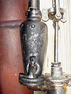
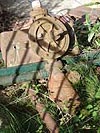
The manufacturers came up with a very simple way of equalising the flow and pressure, through the introduction of the air vessel. This is usually found in the form of a cast iron hollow container connected directly to the delivery side of the pump and as near as possible to the delivery valve. (Some manufacturers incorporated the air vessel within the main casting and it can be difficult to work out where it is.) Here are a couple of examples:
The air vessel works like this: as the plunger starts to descend, the delivery valve opens and, as expected, a pulse of water rushes out at high pressure. But this time the flow divides, most of the water flowing along the delivery pipe, but some trying to enter the bottom of the air vessel - and in doing so it compresses the entrapped air. So immediately the pressure of the pulse is reduced by the action of the water compressing the air entrapped in the air vessel. (And the down side to this is that the total flow or volume of water is momentarily reduced.)
As the plunger reaches the bottom of its stroke, the delivery valve shuts and the pressure drops - and this is when the air vessel does its stuff. The compressed air is now at a higher pressure compared to the line pressure and it starts to push the water that entered the vessel out into the delivery pipe. The delivery valve is shut so the only direction that the water can go is along the delivery pipe, so the flow restarts and continues until the air pressure falls to atmospheric pressure.
But by now the plunger is back up at the top of the barrel, because some poor soul is yanking at the handle, and it's ready for the next down stroke - and so the whole cycle repeats itself. The result is that the pressure and the flow are significantly smoothed out and, in fact, if the speed of the pump is sufficient, then the flow rate and pressure of water becomes almost constant and continuous. Simple, isn't it - but who first came up with this novel idea, I wonder? Once again, it turns out that we need to delve back far beyond the Industrial Revolution - in fact I've read that Ctesibius of Alexandria came up with a design in about 200 BC, and there's evidence from Silchester that the Romans knew of this refinement.
(I'm indebted to Steve Smith for taking the time to explain this all to me, and I've blatantly cribbed his excellent notes in order to produce the above. He has a great web site dedicated to steam pumps at http://www.steampumps.net/)